Digital Circuits and Logic Gates – Binary Number System: NEET MCQs with Answers
15 free questions on Digital Circuits and Logic Gates – Binary Number System for NEET (UG), starting with previous-year NEET and AIPMT questions. Try each one, then tap Show answer for the answer and a short explanation.
Syllabus covered: Binary Number System, Logic gates (OR. AND. NOT. NAND and NOR), Truth Tables, Universal Gates
Question 1
Previous-year questionThe given electrical network is equivalent to [NEET 2017]

- OR gate
- NOR gate
- NOT gate
- AND gate
Show answer
Answer: (B) NOR gate
Explanation: The first gate is a NOR gate, so its output is (A + B)′. Both inputs of the second NOR gate are joined together, so it works as a NOT gate and its output is ((A + B)′)′ = A + B. The last NOT gate inverts this once more, so Y = (A + B)′. Three inversions in all leave the network equivalent to a single NOR gate.
Question 2
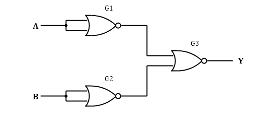
In the circuit shown, input A goes to both inputs of NOR gate G1 and input B goes to both inputs of NOR gate G2. The outputs of G1 and G2 feed NOR gate G3, whose output is Y. The whole circuit behaves as a single
- NAND gate
- AND gate
- NOR gate
- OR gate
Show answer
Answer: (B) AND gate
Explanation: A NOR gate with its two inputs tied together acts as a NOT gate, so G1 and G2 give Ā and B̄. Then G3 gives Y = NOT(Ā + B̄). By De Morgan's theorem this equals A·B, which is the AND operation.
Question 3
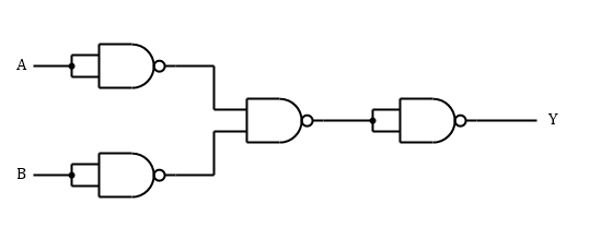
The figure shows a network of four two-input NAND gates. The output Y of the network is the same as that of a single
- NAND gate
- OR gate
- NOR gate
- AND gate
Show answer
Answer: (C) NOR gate
Explanation: The first two gates have their inputs joined, so they give Ā and B̄. The third gate gives the complement of Ā·B̄, which is A + B by De Morgan's theorem. The last gate has its inputs joined and inverts this, so Y is the complement of A + B, the output of a NOR gate.
Question 4
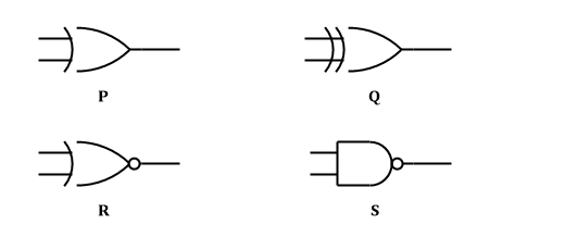
The figure shows four logic gate symbols labelled P, Q, R and S. Which symbols represent the NOR gate and the NAND gate, in that order?
- R and S
- P and R
- P and S
- Q and S
Show answer
Answer: (A) R and S
Explanation: The NOR symbol is the OR shape with a small circle at the output, which is R. The NAND symbol is the AND shape with a small circle at the output, which is S. P and Q have no small circle at the output, so neither of them is a NOR gate.
Question 5
Inputs A and B feed an OR gate, and the output of this OR gate is passed through a NOT gate. The complete arrangement is equivalent to a single
- NOR gate
- AND gate
- NAND gate
- OR gate
Show answer
Answer: (A) NOR gate
Explanation: The OR gate gives A + B and the NOT gate complements it, so the final output is the complement of A + B. This output is 1 only when both inputs are 0, which is the behaviour of a NOR gate.
Question 6
A logic input A is connected directly to one input of a two-input AND gate and, through a NOT gate, to the other input. What is the output Y of the AND gate?
- Always 0, for both values of A
- Equal to A
- Always 1, for both values of A
- Equal to the complement of A
Show answer
Answer: (A) Always 0, for both values of A
Explanation: The two inputs of the AND gate are A and Ā, which always have opposite values. One of them is therefore 0 at every instant. Hence Y = A·Ā = 0 whatever the value of A.
Question 7
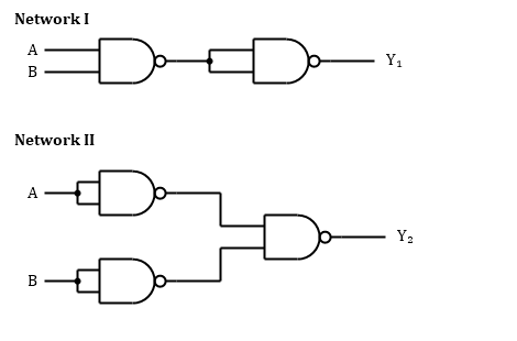
Every gate in the figure is a two-input NAND gate. Networks I and II behave respectively as which single gates?
- AND gate and NOR gate
- AND gate and OR gate
- NAND gate and NOR gate
- OR gate and AND gate
Show answer
Answer: (B) AND gate and OR gate
Explanation: In network I the second gate has its inputs joined, so it acts as a NOT gate and inverts the NAND output, giving Y₁ = A·B. In network II the two input gates act as NOT gates, so the last gate gives the complement of Ā·B̄. By De Morgan's theorem this equals A + B, so Y₂ is the output of an OR gate.
Doing well? Create a free account to take timed tests on this topic and see your weak areas.
Question 8
Logic circuits in a digital computer work with only two voltage levels, low and high. Which number system is used to represent these two levels?
- Binary, which uses only the digits 0 and 1
- Hexadecimal, which uses the digits 0 to 9 and the letters A to F
- Octal, which uses the digits 0 to 7
- Decimal, which uses the digits 0 to 9
Show answer
Answer: (A) Binary, which uses only the digits 0 and 1
Explanation: A circuit with two voltage levels has exactly two states. These match the two digits of the binary system, with 0 standing for low and 1 standing for high.
Question 9
In the logic circuit shown, the three inputs A, B and C are first all held at 0 and are then all changed to 1. The values of the output Y in these two cases are respectively
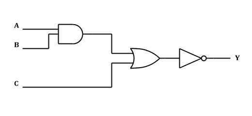
- 1 and 1
- 0 and 1
- 1 and 0
- 0 and 0
Show answer
Answer: (C) 1 and 0
Explanation: The circuit gives Y as the complement of (A·B + C). With all inputs 0, the AND output is 0, the OR output is 0, and the NOT gate gives Y = 1. With all inputs 1, the AND output is 1, the OR output is 1, and the NOT gate gives Y = 0.
Question 10
Only two-input NAND gates are available. What is the smallest number of these gates needed to make an AND gate and an OR gate respectively?
- 1 and 3
- 2 and 4
- 3 and 2
- 2 and 3
Show answer
Answer: (D) 2 and 3
Explanation: A NAND gate with its inputs joined acts as a NOT gate. An AND gate is a NAND followed by such a NOT, which uses 2 gates. An OR gate follows from de Morgan's theorem: invert each input and feed both into a NAND, which uses 3 gates.
Question 11
Input A is connected to both terminals of a NOR gate G1. The output of G1 and a second input B are the two inputs of another NOR gate G2, whose output is Y. For which input condition is Y = 1?
- A = 1, B = 0 only
- A = 0, B = 1 only
- A = 0, B = 0 only
- A = 1, B = 1 only
Show answer
Answer: (A) A = 1, B = 0 only
Explanation: A NOR gate with its inputs joined acts as a NOT gate, so G1 gives the complement of A. A NOR gate gives 1 only when both its inputs are 0, so G2 needs the complement of A to be 0 and B to be 0. This requires A = 1 and B = 0.
Question 12
Only two-input NAND gates are available. The minimum numbers of such gates needed to build a NOT gate, a two-input AND gate and a two-input OR gate are, respectively,
- 2, 2, 3
- 1, 3, 2
- 1, 2, 3
- 1, 2, 4
Show answer
Answer: (C) 1, 2, 3
Explanation: A NAND gate with its inputs tied together is a NOT gate, so one gate is enough. AND needs a NAND followed by such an inverter, which makes two gates. OR needs each input inverted before a final NAND, because NOT(Ā·B̄) = A + B, which makes three gates.
Question 13
Input A passes through a NOT gate. The output of this NOT gate and input B feed a NAND gate, whose output is Y. For which single input combination is Y = 0?
- A = 1, B = 0
- A = 0, B = 0
- A = 0, B = 1
- A = 1, B = 1
Show answer
Answer: (C) A = 0, B = 1
Explanation: A NAND gate gives 0 only when both of its inputs are 1. Its inputs here are Ā and B, so Ā = 1 and B = 1 are required, which means A = 0 and B = 1.
Question 14
Inputs A and B feed an OR gate, and B also passes through a NOT gate. The OR output and the NOT output feed an AND gate, whose output is Y. The expression for Y reduces to
- A·B̄
- Ā·B
- A·B
- A + B̄
Show answer
Answer: (A) A·B̄
Explanation: The network gives Y = (A + B)·B̄ = A·B̄ + B·B̄. Since B·B̄ = 0 for every value of B, the expression reduces to Y = A·B̄.
Question 15
Inputs A and B feed an OR gate and the same two inputs also feed a NAND gate. The outputs of these two gates feed an AND gate, whose output is Y. For which inputs is Y = 1?
- Whenever A and B are different
- Whenever A and B are equal
- Only when A = B = 0
- Only when A = B = 1
Show answer
Answer: (A) Whenever A and B are different
Explanation: Y = (A + B)·NOT(A·B). For A = B = 0 the OR output is 0, so Y = 0. For A = B = 1 the NAND output is 0, so Y = 0. For (0, 1) or (1, 0) both the OR and NAND outputs are 1, so Y = 1.
Want more Digital Circuits and Logic Gates – Binary Number System questions?
E-GYAN NIDHI has 76 questions on this topic and 63,000+ in total, all free: timed CBT tests, NEET marking and instant analysis.
Register free Free Sunday Mock Test